Helping you with your engineering courses.
Take a look at the most recent problem that we solved below. Or click on Subjects or check out our YouTube channel to view more problems.
|
Draw the shear and bending-moment diagrams for the beam and loading shown and determine the maximum normal stress due to bending. 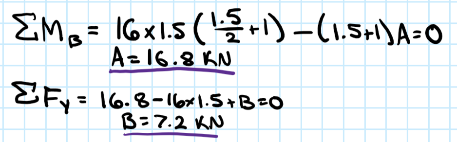 Shear Diagram Step 1: Determine the reactions at A and B.  Step 2: Draw out the shear diagram The shear at A is equal to the reaction at A. 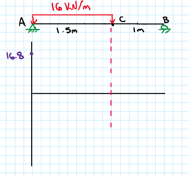 A uniformly distributed load (w) corresponds to a linearly sloped line of the shear diagram. In this problem, there is a line between points A and C with a negative slope of 16 kN/m. First let's determine the shear at point C. 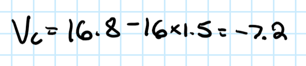 Connect these two points. 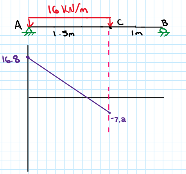 There are no loads or supports between points C and B, therefore there is no change in shear. 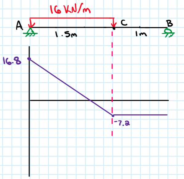 There is an upward reaction of 7.2 kN at B, so the shear increases by 7.2 kN at B. The shear diagram ends at 0. This is our final shear diagram. 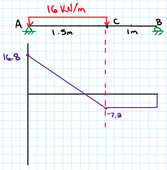 Moment Diagram Step 1: Divide the shear diagram into 3 areas. 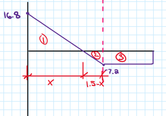 Step 2: Use similar triangles to determine x. 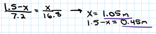 Step 3: Since the moment is the area under the shear diagram, determine the area of each section under the shear diagram. 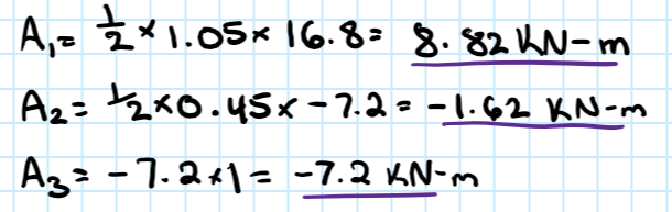 Step 4: Draw out the moment diagram. The moment at "x" is equal to the area of the 1st section. A linearly sloped line on the shear diagram corresponds to a curved line on the moment diagram. 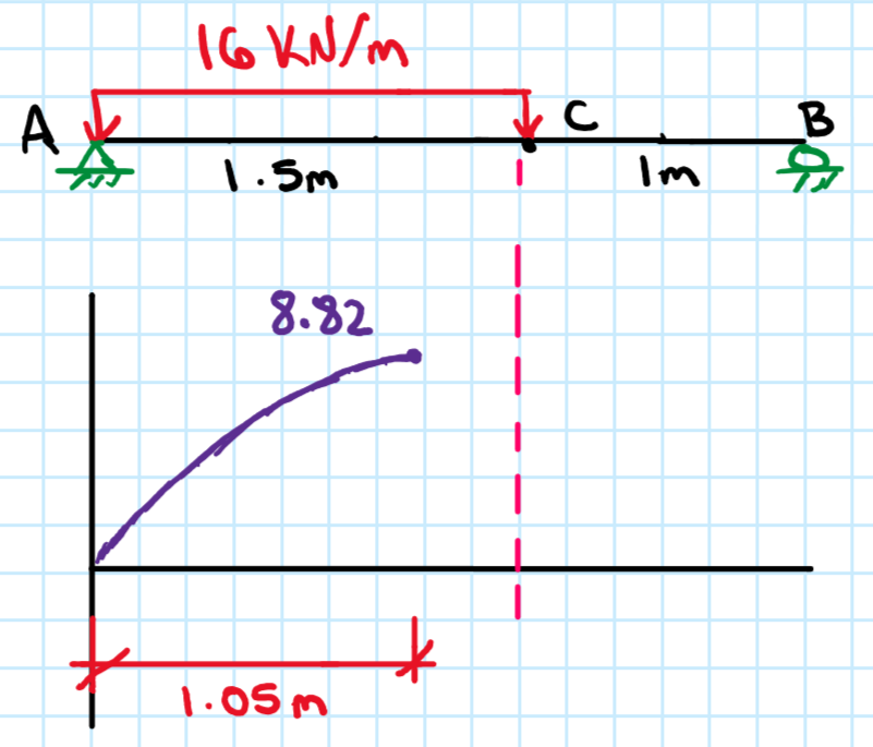 Since the area of the second section was -1.62 kN-m (it's negative because the area is below 0 on the shear diagram) the moment is decreases by 1.62 kN-m. 8.82 - 1.62 = 7.2 KN/m 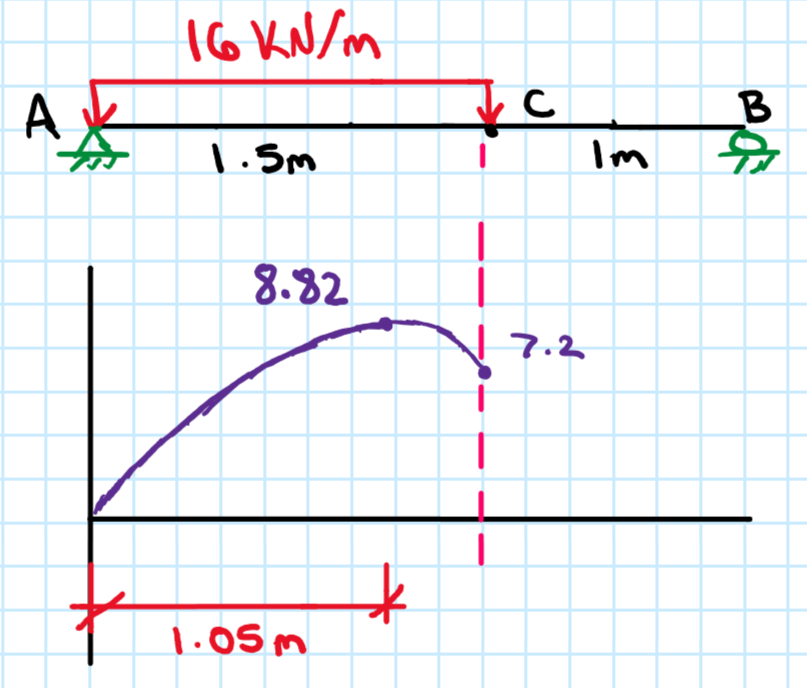 Since the area of the third section was -7.2 kN-m, the moment is decreases by 7.2 kN-m. A flat line on the shear diagram corresponds to a linearly sloped line on the moment diagram. This is our final moment diagram.  Maximum Stress According to the moment diagram the maximum moment on the beam is 8.82 kN-m. Look up the section modulus (S) for an S150x16.5 (be sure to use metric) and use the bending stress formula to determine the maximum bending stress. 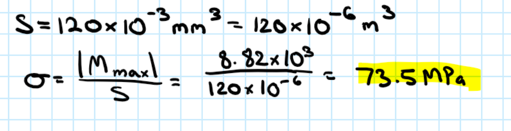 ANS = norm. stress: 73.5 MPa
0 Comments
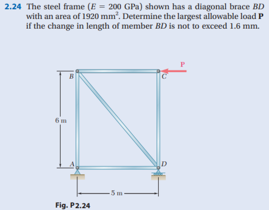
Assume that the retaining wall shown in Figure 13.39 is frictionless. For each problem, determine the Rankine active force per unit length of the wall, the variation of active earth pressure with depth, and the location of the resultant. 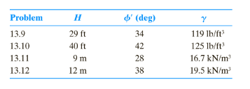 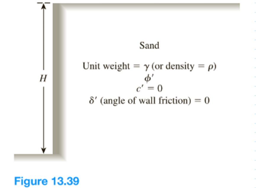 We did a video in this, click here. The plastic block shown is bonded to a rigid support and to a vertical plate to which a 55-kip load P is applied. Knowing that for the plastic used G=150 ksi, determine the deflection of the plate.  We did a video on this, click here. Streams of water from two tanks impinge upon each other as shown in Fig. P3.36. If viscous effects are negligible and point A is a stagnation point, determine the height h. 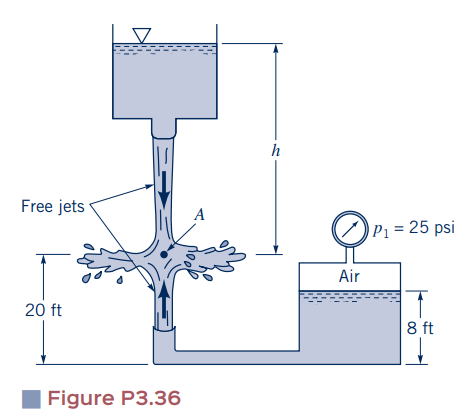 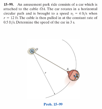 Step 1: Develop an equation that expresses how the radius changes over time and calculate the length of the radius at 3 seconds. 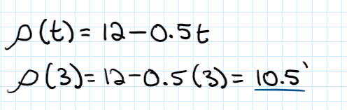 Step 2: Apply conservation of angular momentum to calculate the car's velocity in the tangential direction at 3 seconds. 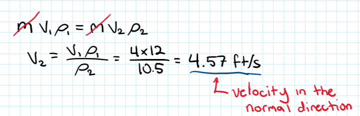 Step 3: Since the car's velocity in the normal direction is already given as 0.5 ft/s we can calculate the magnitude of the car's velocity. 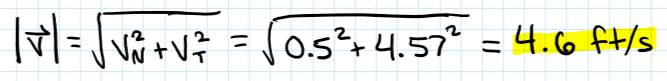 ANS = 4.6 ft/s
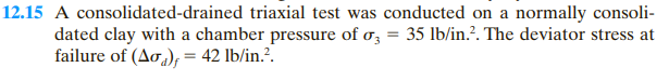 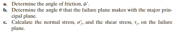 Part A Step 1: Determine the radius of Mohr's circle. 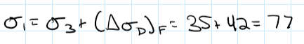 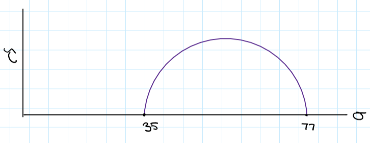 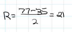 Step 2: Determine the distance between the origin and the center of Mohr's circle 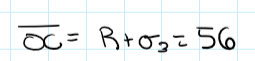 Step 3: Calculate the angle of friction. 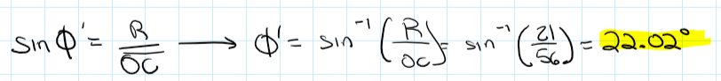 Part B Calculate angle of the failure plane. 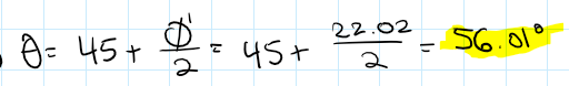 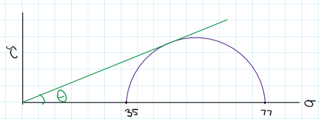 Part C Step 1: Calculate alpha. 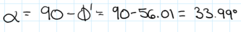 Step 2: Calculate the shear stress on the failure plane. 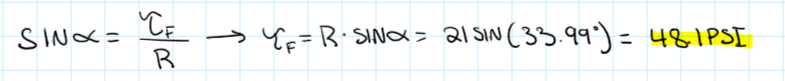 Step 3: Calculate the normal stress on the failure plane. 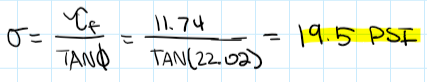 ANS
A) 22.02 degrees B) 56.01 degrees C) shear stress: 48.1 psi normal stress: 19.5 psi In a consolidated-drained triaxial test on a normally consolidated clay, the specimen failed at a deviator stress of 27 psi. If the effective friction angle is known to be 23 degrees, what was the effective confining pressure at failure? Solution The specimen failed in shear at 27 psi. 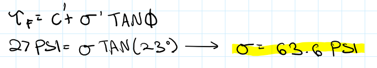 ANS = 63.6 psi
Results of a standard Proctor compaction test on a silty sand are shown in the figure below. 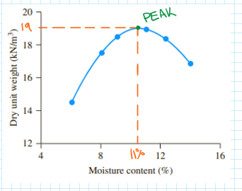 A) Find the maximum dry unit weight and optimum moisture content. B) What is the moist unit weight at optimum moisture content? C) What is the degree of saturation at optimum moisture content? Given: Gs=2.69. D) If the required field dry unit weight is 18.5 kN/m^(3) what is the relative compaction? E) What should be the range of compaction moisture contents in the field to achieve the above relative compaction? F) If the minimum and maximum void ratios are 0.31 and 0.82, respectively, what is the relative density of compaction in the field? Part A The maximum dry unit weight and optimum moisture content occurs at the peak of the graph.  The maximum dry unit weight is roughly 19 kN/m^(3) and the optimum moisture content is around 11% Part B Use one of the derived equations to calculate the moist unit weight. 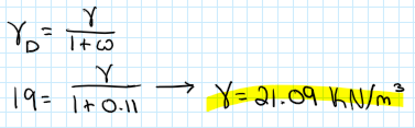 Part C First calculate the void ratio. 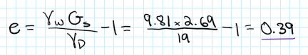 Then use one of the derived equations to calculate the degree of saturation. 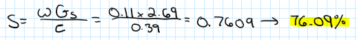 Part D Relative compaction: 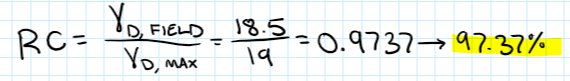 Part E First, we must find the unit weight that will allow us to achieve a 97% relative compaction. 97% of 18.5 kN/m^(3) is about 18 kN/m^(3). Therefore, the moisture content range is where 18 kN/m^(3) is achieved. 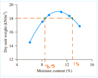 The range is between 8.5% and 13%. Part F Relative density: 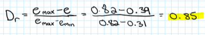 ANS
A) maximum dry unit weight: 19 kN/m^(3) optimum moisture content: 11% B) moist unit weight: 21.09 kN/m^(3) C) S=76.09% D) RC=97.37% E) 8.5% to 13% F) Dr=0.85 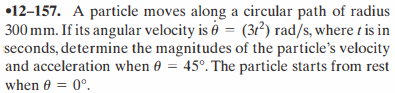 Step 1: Draw a picture of the situation and gather the information that is given and what we need to find. 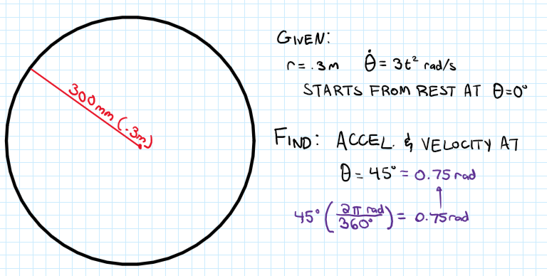 Step 2: Set up a differential equation to find the time, t, at which the particle reaches 0.76 radians. 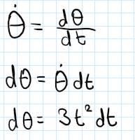 Step 3: Solve for time, t. 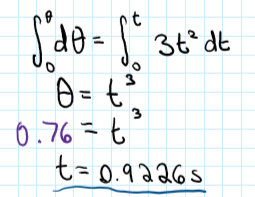 Step 4: Determine the radial and theta components of velocity at this very instant. 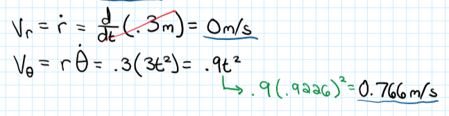 Step 5: Calculate the magnitude of the velocity. 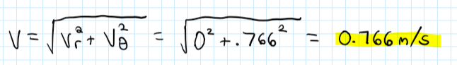 Step 6: Determine the radial and theta components of acceleration at this very instant. 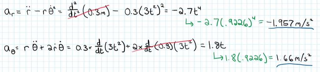 Step 7: Calculate the magnitude of the acceleration. 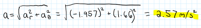 ANS = velocity: 0.766m/s accel.: 2.57m/s^2
Determine the plastic moment Mp of a steel beam of the cross section shown, assuming the steel to be elastoplastic with a yield strength of 240 MPa. 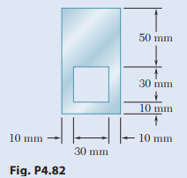 Step 1: Determine the location of the neutral axis (NA). 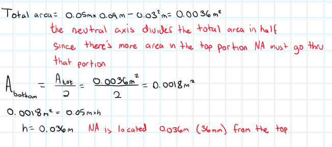 Step 2: We will divide the cross section into different areas and draw a stress diagram to determine the location of the resultant forces acting on each area. Remember, when a material is plastic that means everything has yielded. 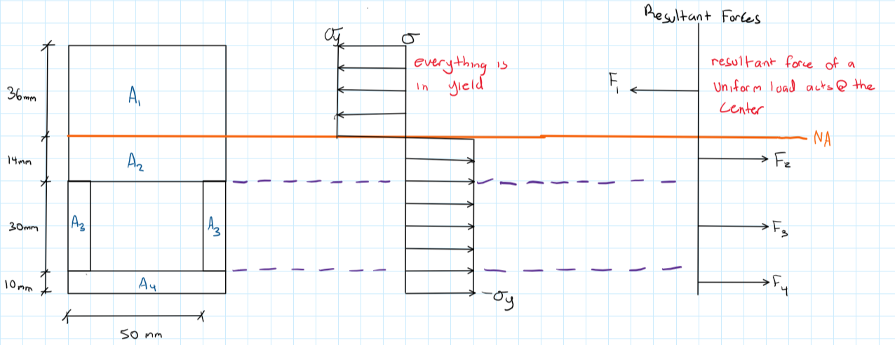 Step 3: Determine the magnitude of each force. 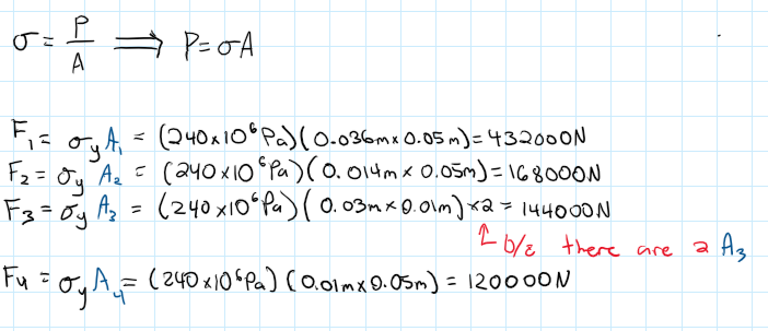 Step 4: Determine each force's lever arm. 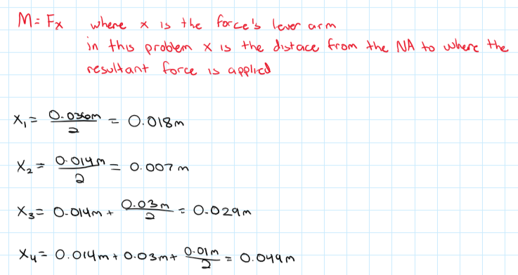 Step 5: Calculate plastic moment. 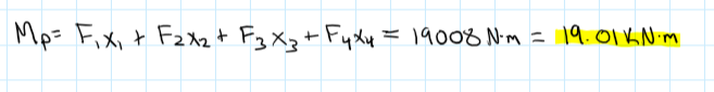 ANS = 19.01 kN-m
Water flowing from the 0.75-in.-diameter outlet shown in Video V8.15 and Fig. P3.45 rises 2.8 in. above the outlet. Determine the flowrate. 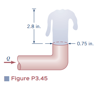 Step 1: Determine our points of interest to use in Bernoulli's equation. 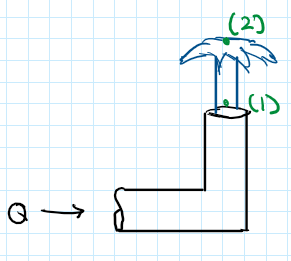 Point 1 is the moment that the fluid exits the pipe and point 2 is the fluid at its maximum height. By setting our points this way we can make point 1 our datum and make the following assumptions: 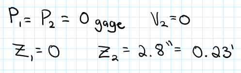 Step 2: Write out Bernoulli's equation. 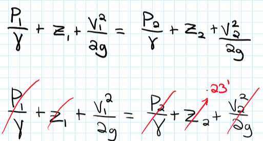 Step 3: Solve for the velocity at point 1. 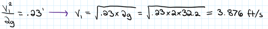 Step 4: Solve for the flow rate, Q. 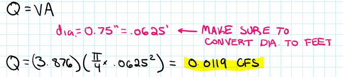 ANS = 0.0119 CFS
The solid shaft shown is formed of a brass for which the allowable shearing stress is 55 MPa. Neglecting the effect of stress concentrations, determine the smallest diameters dAB and dBC for which the allowable shearing stress is not exceeded. 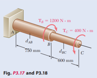 We did a video on this, click here. Two solid cylindrical rods AB and BC are welded together at B and loaded as shown. Knowing that d1=30 mm and d2=50 mm, find the average normal stress at the midsection of (a) rod AB, (b) rod BC. 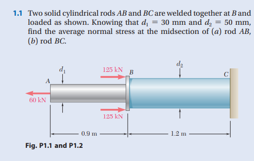 We did a video on this, click here. |
AuthorAs a civil engineer student, I found a hard time trying to find a one stop shop for help in all my courses. That's why I am here trying to fill in that void! Archives
January 2023
Categories |
 RSS Feed
